1. The fault!
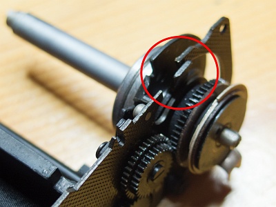
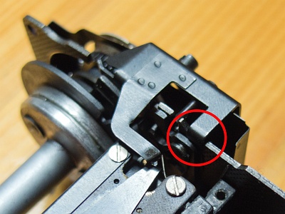
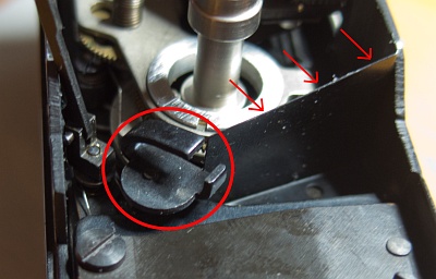
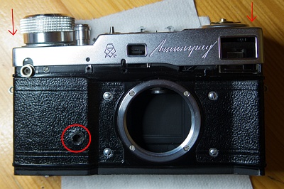
It was this lever (in the red circle). It has moved out of its correct position and blocked the release process.
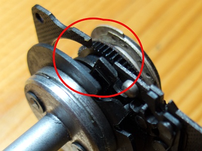
The correct position of the lever is below the shutter housing. Only then can it move.
The Leningrad has a similar modular design to the Start. The shutter can be completely removed from the housing.
2. Self-timer
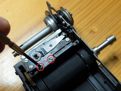
When troubleshooting, I also removed some unnecessary parts, including the self-timer.
It is only attached with 2 screws, in contrast to the self-timer of the Zorki 4, which is held in place by 3 screws. It is also constructed slightly differently.
3. Trigger unit
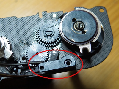
The fault then came to light under the cover plate of the gear wheels.
The bent part next to the two cogwheels continues the film counter.
The sheet metal plate that covers the gear wheels is placed on top, and the large flat spring is placed over it. Both parts are screwed together with the spacer in a circle in the housing.
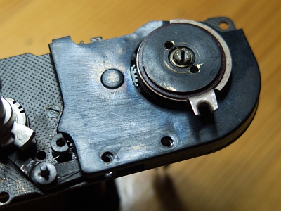
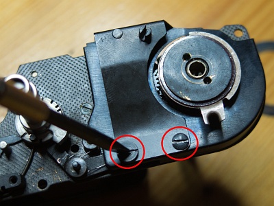
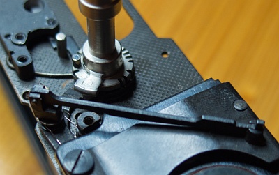
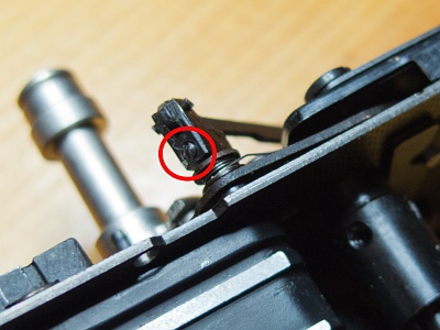
The nose of the flat spring must come to rest on the front under the housing frame (circle).
When the shutter is released, the entire spring is pressed down. It also sets the self-timer in motion when it is cocked.
The long release lever is now reattached. It is pressed down by the release button and actuates, among other things, the lever that is also used for the "B" setting on the top (see "Small parts" below).
The lever is secured with a small grub screw (circle).
4. Shutter speed control lever
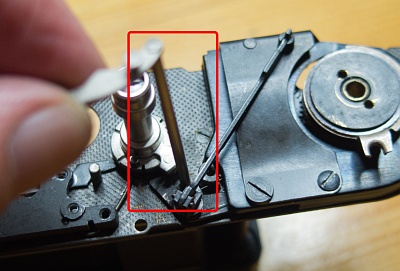
Or what else do you call it?
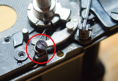
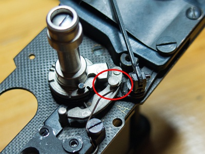
However, it must be inserted from above and come out of the housing at the bottom.
The spring that pushes it down must be reattached and brought into the correct position.
5. Slow speed mechanism
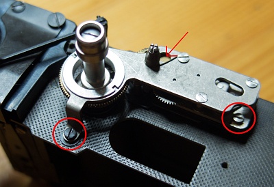
Now the slow time mechanism can be refitted. This is a little fiddly, as it is under spring tension and should not come off if possible.
On the Leningrad, it is secured with 3 screws because of the hard and abrupt tensioning process.
One of the screws (arrow) can only be reached by moving the large gear wheel around the timing lever into the correct position.
6. Housing assembly
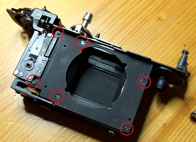
First screw on the front cover plate. It is fastened with 6 screws.
Before doing so, it is advisable to clean and re-oil the transport gear wheels (one made of brass can be seen below).
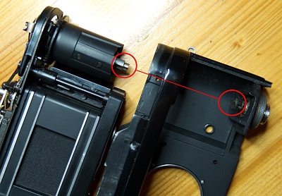
The axle is then inserted and the film take-up drum attached. There is a slot at the bottom of the axle which must be inserted into the matching pin of the rewind lock at the bottom of the housing.
The shutter module can now be pushed into the housing.
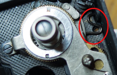
Four screws each hold the catch from above and from the front.
The small curved spring, whose purpose is unclear to me, must be inserted under one of the screws. Perhaps it serves as a brake during the automatic tensioning process.
I temporarily secured the lever from 4. with an adhesive strip, otherwise it would fold out and get in the way.
7. Rangefinder
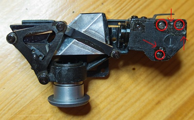
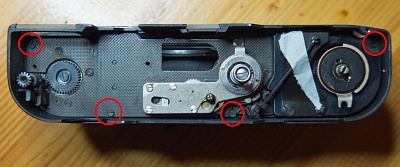
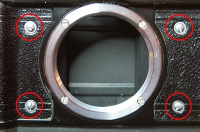
The rangefinder can be removed and adjusted as a whole. There are 3 screws (circles) for vertical adjustment, each secured by a grub screw (arrows).
This allows the height offset and the inclination of the sectional view to be adjusted. Quite a tricky matter.
As with almost all other cameras, the horizontal adjustment is made from the front using a concealed screw.
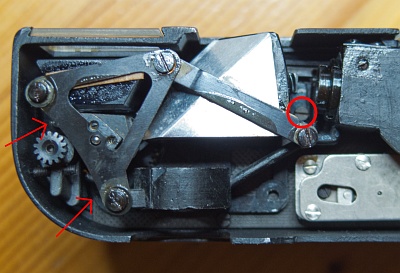
It is held in place by 3 screws. The two on the left are located quite deep in the housing and are difficult to reach.
8. "Small parts"
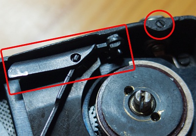
The lever on which the shutter release presses and the connection for the flash still have to be attached.
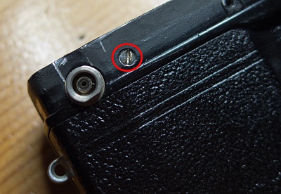
The release lever is fixed from the front with a screw, the flash connection from above.
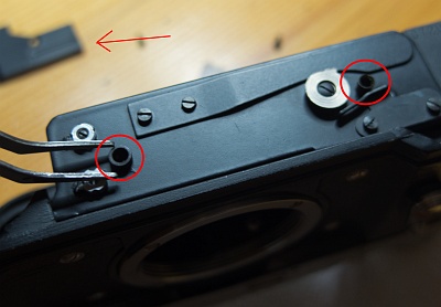
The long lever from 3. is inserted into the hole provided (circle). It goes all the way down through the housing.
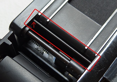
The light trap (the small plate, arrows) must also be refitted.
9. Cover on top
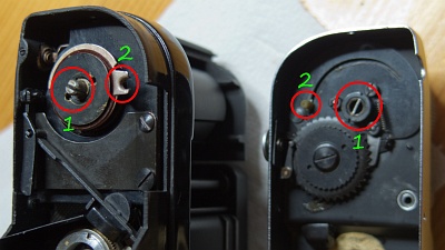
Now it's time to place the cover with the spring motor on the housing. The slot in the transport drum must be engaged in the pin that is attached to the spring in the transport button (1). To do this, turn the transport knob to the correct position.
You must also ensure that the small catch for the flash delay setting is seated in the slot (2).
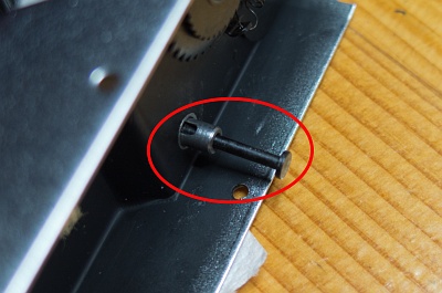
Don't forget to insert the pin for the cable release into the release button from below.
If everything fits, the cover can be fitted quite easily. Then refit the self-timer.
Now the cover at the bottom is still missing (arrow in the background). The two spacers must be in the right places (the shorter one on the left).
10. You made it!
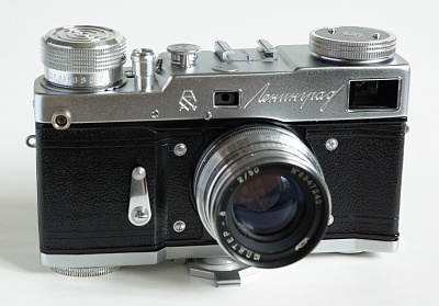
The speed button and the rewind button with the film marker disk are still missing.
Put the cover screws back in, put the back on - et voila.
By the way, you don't need to worry that the spring will fly around your ears when you remove the cover. The spring is located inside the large transport button and remains there.
