1. First impression
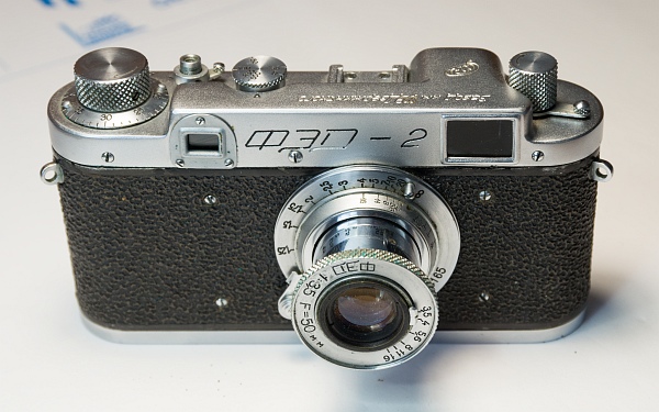
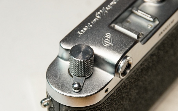
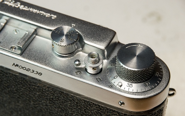
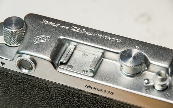
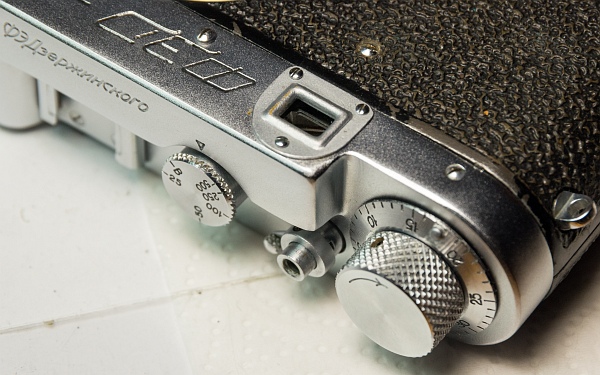
A very respectable camera without any dents or obvious missing parts. In the course of disassembly, however, parts were missing, defective or tinkered with due to improper handling (screwed-up screw heads are very popular).
And unfortunately, it has a totally defective shutter. The cloths need to be replaced.
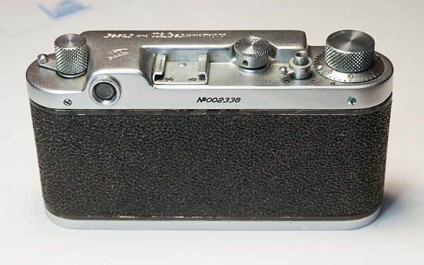
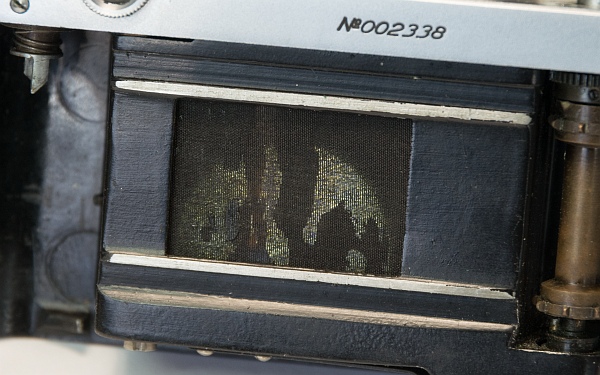
2. Disassemble
2.1 Remove cover
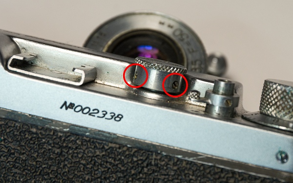
So let's start taking them apart. Let's start with the outer parts.
The first step is to remove the two speed wheel screws. It can then simply be pulled off (left).
Then we unscrew the rear eyepiece (bottom left).
Remove the two screws of the rewind latch (of which there was only one on this camera) and take it off and the shutter release (below).
Next we remove the accessory shoe. Which unfortunately was attached with the wrong screws (round head instead of flat head) (at the bottom).
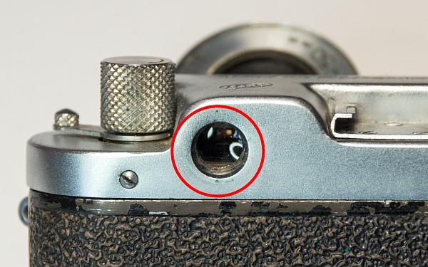
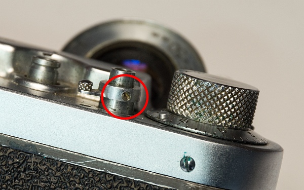
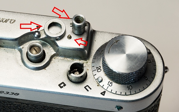
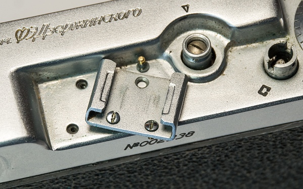
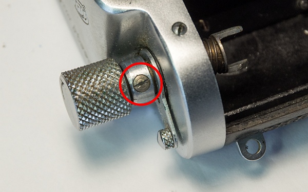
Unscrew the screw that holds the rewind crank in place. Pull out the knob and remove the ring through which the screw went.
The fork for the film cartridge can then be pulled out. There is a spring on it and normally a washer, but this was missing here.
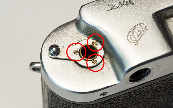
The diopter adjustment is attached to the FED pre-series with 3 small screws, which makes reinstallation much easier. Unfortunately, one of the screws (the upper one) is completely screwed up here, I had to drill it out later with a Dremel (left).
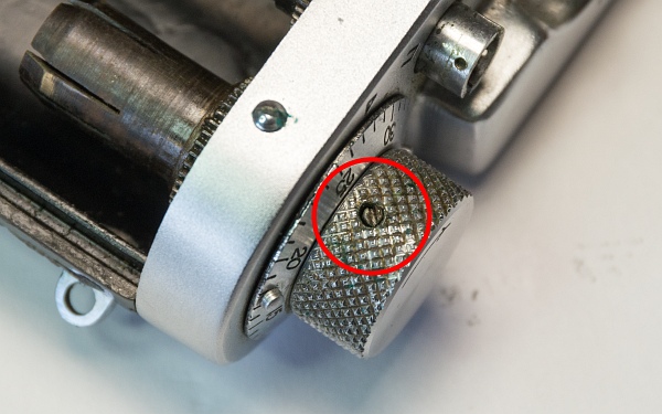
Now loosen the screw on the tensioning knob. Hold the gear wheel inside and turn the tension knob counterclockwise. It can be quite tight (bottom left).
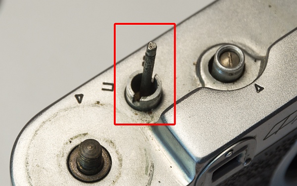
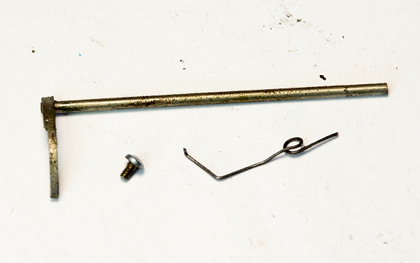
By now, the silver release rod should have fallen towards you. But don't panic, it doesn't fit anywhere else (below).
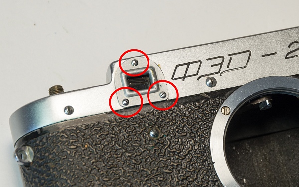
We remove the cover of the rangefinder eyepiece and can then take off the cover after removing the screws on the front and back (2 at the back, 3 at the front).
2.2 Remove shutter
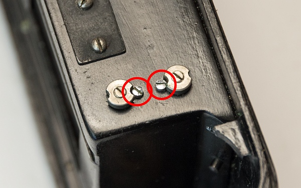
So, the shutter has to be removed to get to the cloths. First, loosen the springs so that you can remove the shutter in a quasi-tensioned state (this makes reassembly much easier).
The first step is to remove the locking screws of the shutter springs. Then loosen the screws (attention, left-hand thread!) inside the nuts and release the two springs.
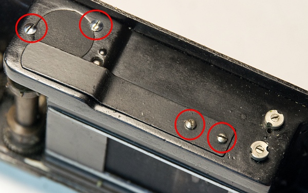
The shutter spring is released by removing the two lower screws. Inside, the lower light trap and a threaded plate fall out.
The two upper screws only hold the cover of the gear wheel under the large drum.
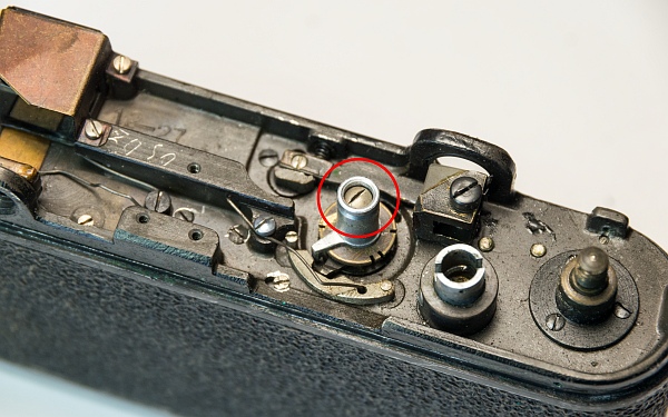
Wind the shutter and loosen the large screw in the middle. The knob for adjusting the speeds can then be removed (left).
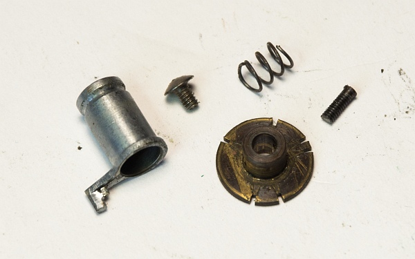
Underneath it, remove the disk with the notches for the different speeds, which is secured by a screw. The disk can then be pulled off over the axle of the drum (bottom left).
The parts in detail (below).
Now pull out the speed delay lever and unscrew the spring (bottom left).
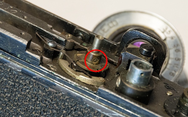
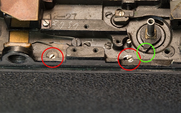
The two screws marked in red hold the shutter from above. They must be removed.
Important! Be sure to mark the position of the lever in the green circle! It must be in this position when it is installed.
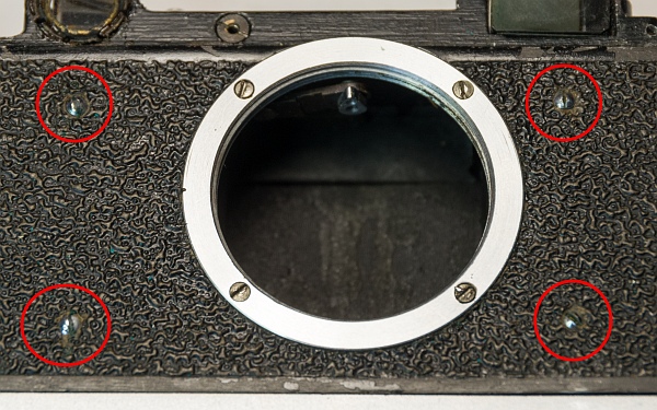
Remove the 4 marked screws on the front (bottom left).
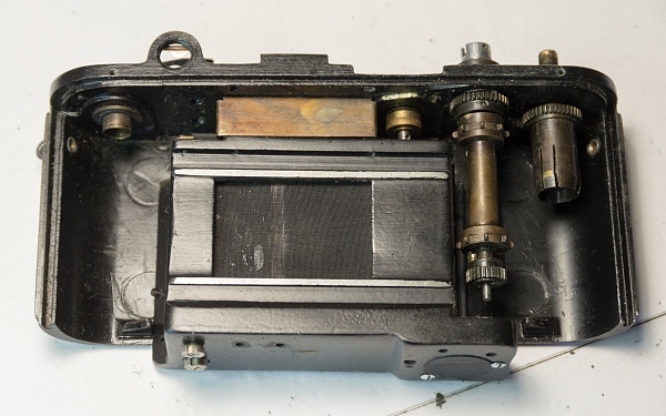
The shutter box can then be removed (bottom).
2.3 Removing the winding mechanism
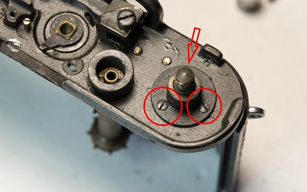
The entire winding mechanism (winding knob, gears, spiked roller and pawl) must be removed and cleaned. This is where the hardened old grease from the USSR is usually found. This camera, on the other hand, has been heavily re-oiled at some point, as is easy to see.
Remove the 3 screws. They hold the lower part of the winding knob, i.e. the part on which the film take-up spool is attached.
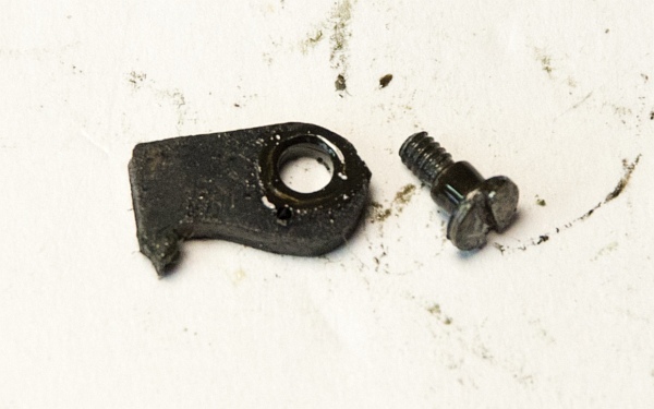
Below the tensioning knob is the locking pawl, which prevents the curtain from rolling back after tensioning due to the spring force. The locking pawl is a new feature compared to the FED 1, which instead had a spring that tended to wear out.
As you can see, everything is drenched in oil.
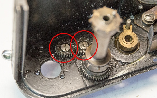
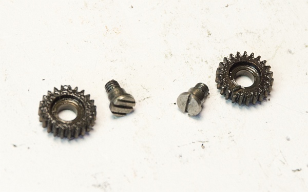
These two gears must be removed. The one on the left has a normal right-hand thread, but the other has a left-hand thread. Caution! However, its screw is marked separately by 3 slots.
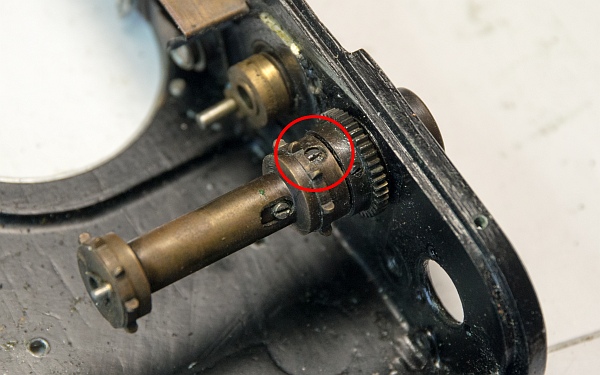
We remove the marked screw and then pull off the spiked roller (below).
2.4 Disassemble the shutter
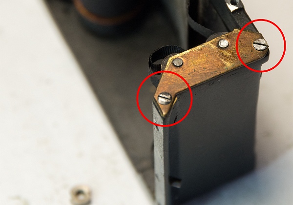
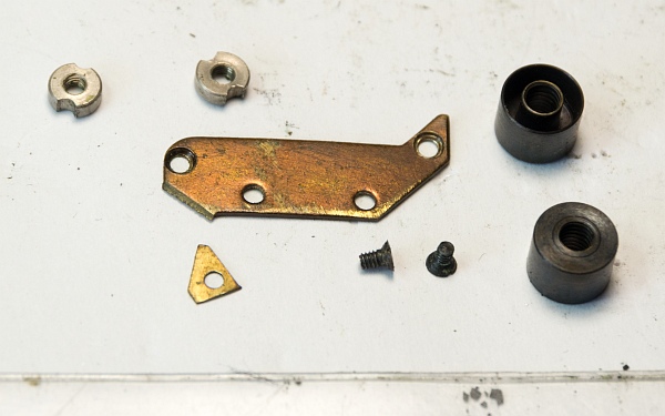
A special feature of the pre-series is that the two rollers of the first and second curtains are not hooked into the housing cover, but that there is a kind of locking cage in the form of a cover that holds the two rollers. This makes reinstallation much easier.
The parts in detail. At the top left are the nuts for adjusting the spring tension, on the right are the two rollers for guiding the locking straps of the second curtain (bottom left).
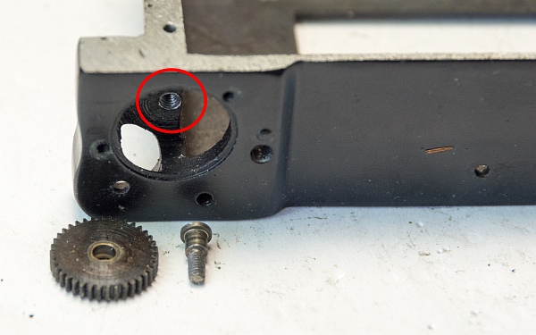
Then we remove the large gear wheel at the bottom of the locking box. This screw can be very tight, so please do not use force. If it breaks off, the camera will only be good as a paperweight (bottom).
2.5 Measure cloths
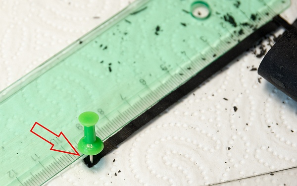
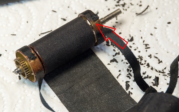
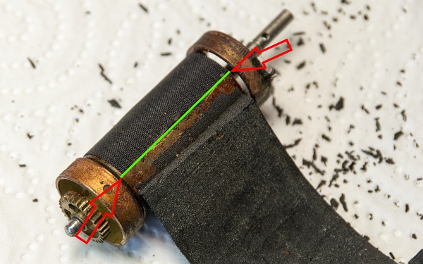
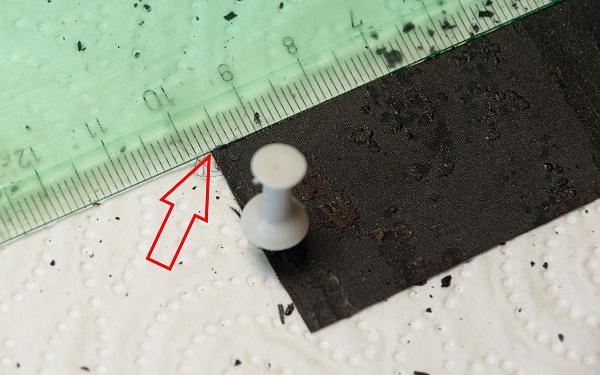
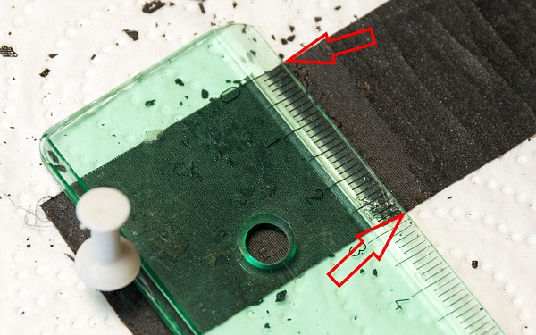
There are a total of 5 markings and measurements that are important:
1. The length of the strips of the first (shorter) curtain that are glued to the large outer drum (left).
2. The position of these strips in the same place (bottom left).
3. The position of the second (longer) curtain on the large drum (bottom).
4. The length of the second curtain that is glued to the large drum (bottom left).
5. The width of the curtain (bottom).
We have to note down all these measurements and adjust the new curtain to them.
Oh, yes. Look at all the crumbs, the old curtains are practically falling apart in your hands ;-)
2.6 Cleaning drums
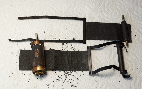
The old cloths have been removed from the large and small drums (left).
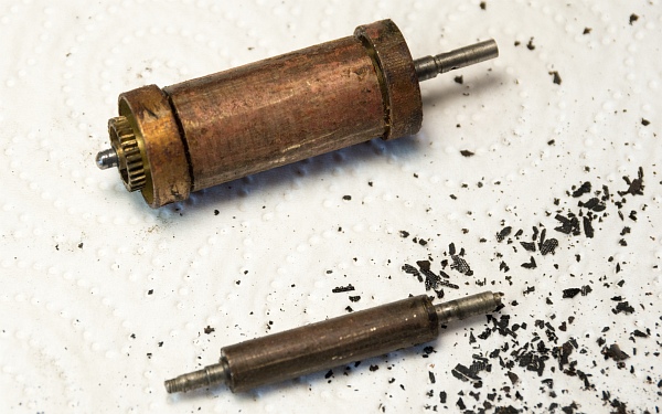
The rest of the sealing cloth material must be scraped off both drums (bottom left).
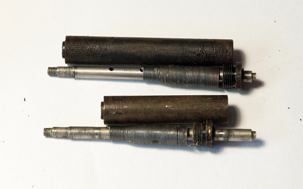
Finally, we open the two tension spring housings; the springs can be unscrewed at the top (bottom). The tension springs are usually fine; I have only had one that was overtightened, which was probably tensioned in the wrong direction.
3. Interim result
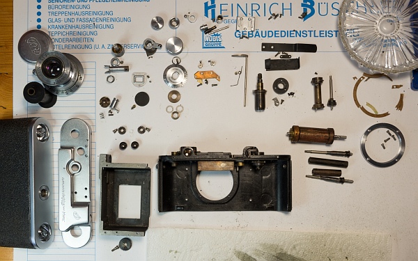
All parts have now been cleaned and polished. I use cleaning solvent and a toothbrush to clean them, which removes even the most stubborn dirt. The metal parts are then cleaned again in an ultrasonic bath.
To polish the chrome parts, I use NevrDull, a polishing cloth from the motorcycle accessories range. This gives the parts a very nice finish.
4. Assembly
4.1 Reassemble the cocking mechanism
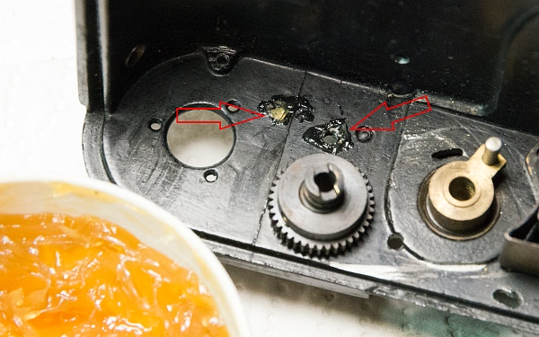
After cleaning, the puzzle must now be reassembled.
Before we take care of new shutter cloths and installation, we first reassemble the tensioning mechanism.
First, we reinsert the small gears. Remember, one is screwed in with a left-hand thread and the other with a right-hand thread! A little grease will make them run smoothly (left).
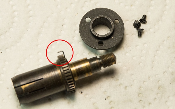
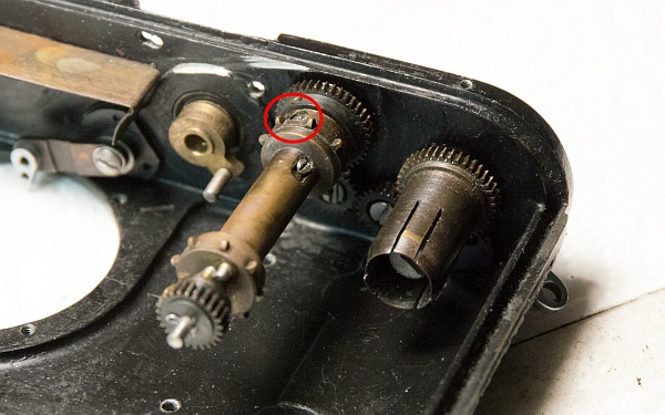
Reinsert the film take-up spool. Again, a little grease won't hurt. Note: The small spring in the red circle will play a role later (bottom left).
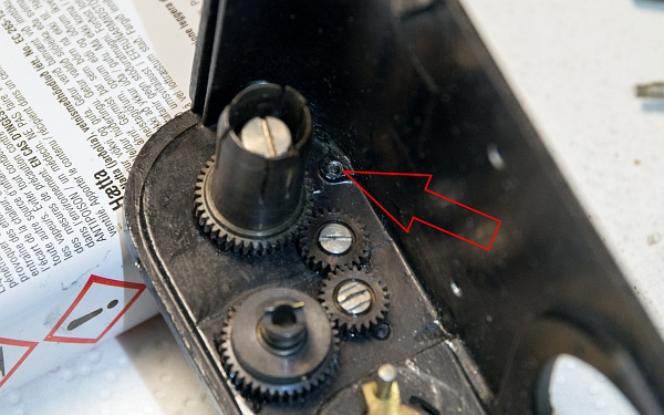
Once the gears are assembled, the pawl must be reinserted. This is a bit of fiddly work... (bottom).
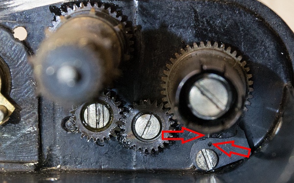
The small spring at the top of the red circle must be inserted into the hole in the pawl (see arrows). Only then will it function correctly (bottom left).
Now screw the sprocket roller back on (bottom).
4.2 Adjusting the cloths
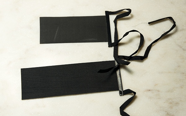
Now we have to prepare and cut the new cloths, stick them to the two drums, and then install them in the shutter box.
I usually cut the new cloths from a piece of shutter cloth (ebay - Nobbysparrow), as 99% of the straps are still in good condition. However, I was given these prefabricated cloths some time ago and now wanted to use them.
In addition, the fold around the flat metal rods could become too thick if the cloths are glued around them, so that the shutter no longer works properly. With the sewn cloths, the metal part is much thinner and narrower.
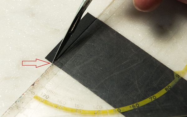
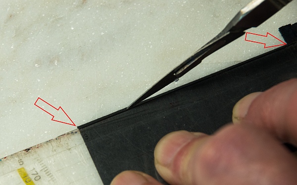
1. Shorten the second curtain to the correct length (bottom left).
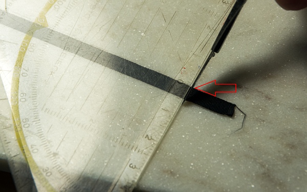
2. Adjust the length of the straps on the first curtain (bottom).
3. Finally, cut the cloths to the correct width (bottom left).
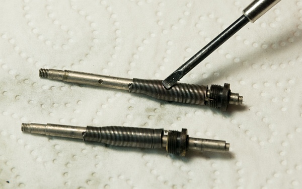
Finally, we lubricate the tension springs a little so that they don't squeak (bottom). Then the springs can be screwed back into their sleeves. Be careful not to mix them up!
4.3 Glue on the ribbons
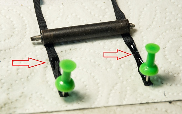
The position of the straps of the second curtain on the sleeve is irrelevant. However, care must be taken to ensure that they roll up straight (left). Pattex, for example, is a suitable adhesive.
The straps of the first curtain, which have been cut to the correct length beforehand, must be positioned exactly (bottom left).
Care must be taken to ensure that the curtain is rolled up exactly parallel, otherwise it will run crookedly (bottom).
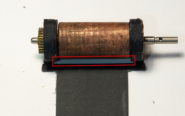
4.4 Glue on the curtains
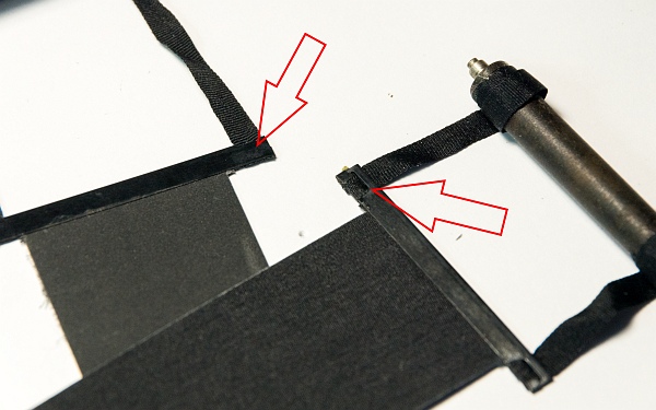
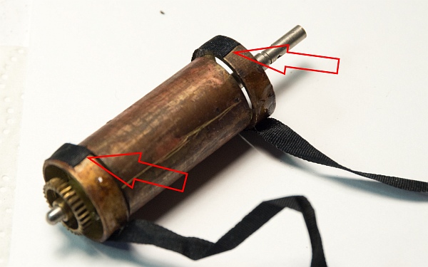
The straps and cloths must be attached so that the smooth sides of the two metal bars slide past each other! Important! Otherwise, the shutter will not work properly. This issue caused me some delays with another camera... (left)
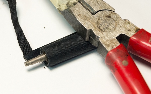
Glue the first curtain onto the shorter sleeve. The position of the cloth on the sleeve does not matter. Weigh down the newly attached cloth until the adhesive has set (bottom left).
Slide the long curtain over the shorter one under the large drum. It can then be attached at the previously marked position. The red frame shows how the cloths are slid over each other (below).
4.5 Reassemble the shutter
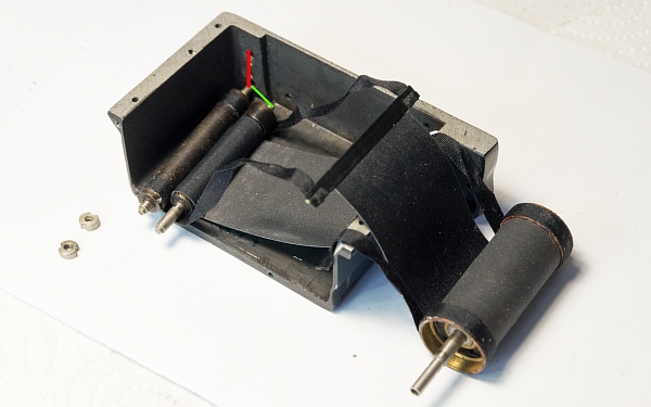
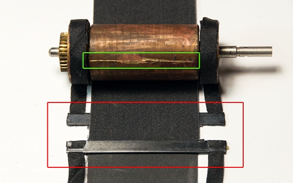
Place the fully assembled cloths in the shutter box as follows. The second curtain goes at the top (red line), the first at the bottom (green line) (left).
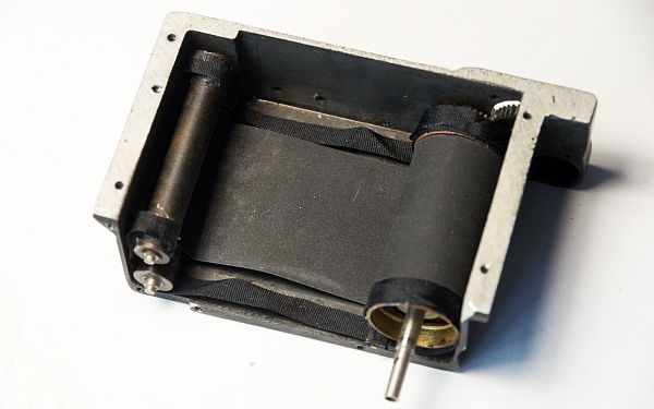
All drums are now in place. The thin drums have been reattached with the small nuts (bottom left).
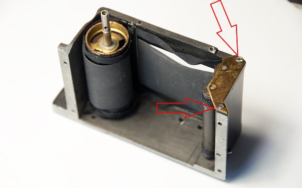
Now close the cage again and insert the shutter into the housing. Secure the driver on the top at the previously marked point with masking tape, for example, so that it does not slip. With the large drum turned in the correct direction so that the pin fits into the hole, fiddle the closure back into the housing. This is much more difficult with the FED 2 than with a FED 1 or Zorki 1, as the housing cannot be completely removed (below).
Further information on installing the drum and resetting the shutter speeds can be found here.
4.6 Trigger and speed control
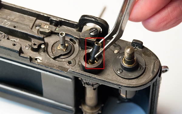
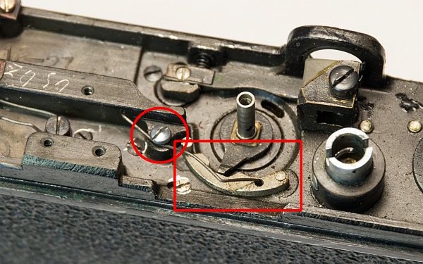
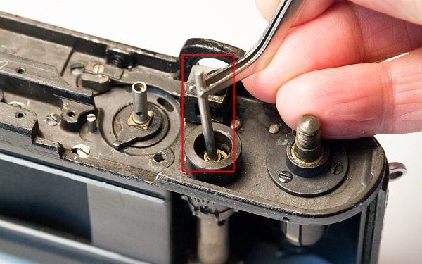
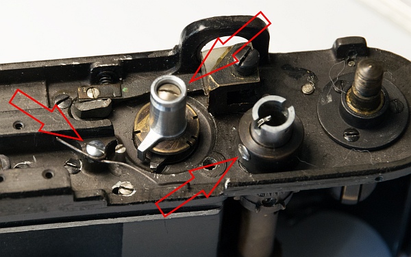
Reassemble the inner workings of the trigger (left and bottom left).
Reinstall the speed disc, the knob for adjusting the speeds, and the spring that presses down on the drive lever. Also reattach the collar to the trigger (bottom).
4.7 Diopter adjustment and cover
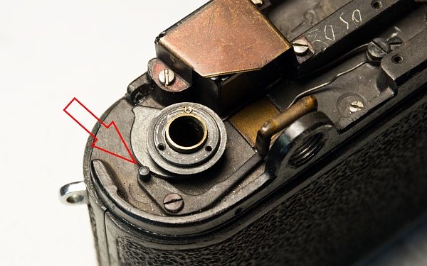
The diopter adjuster is inserted. Pull the black lever slightly to the left and place the diopter adjuster on the axis with the spring.
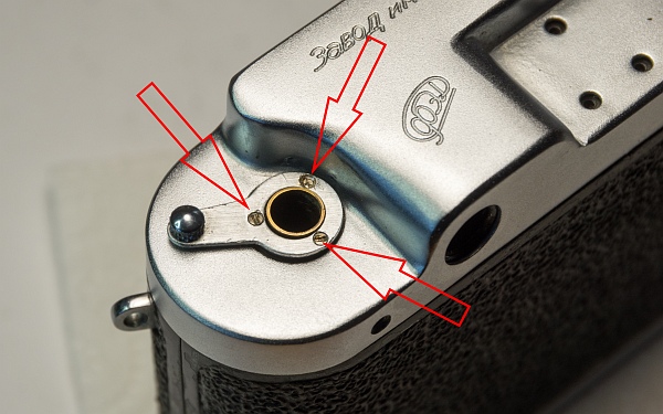
Now the cover can be replaced. The diopter adjustment lever is now reattached with the 3 small screws. Check whether the lens inside moves behind the eyepiece opening when you adjust the lever.
4.8 Adjusting the rangefinder
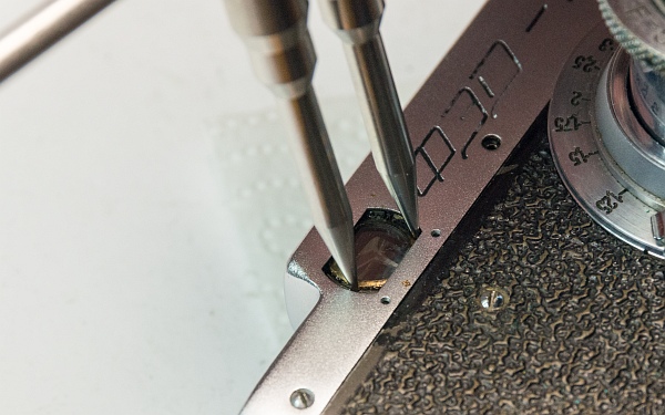
After reattaching the lens mount (make sure that the brown wax paper discs are correctly positioned for fine adjustment), it is advisable to adjust the vertical and horizontal offset of the rangefinder.
The vertical offset can be adjusted using a spanner device.
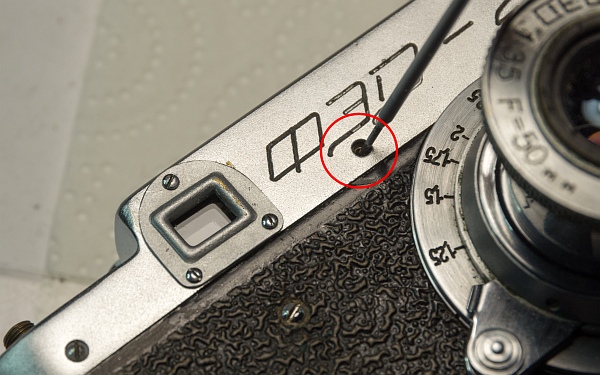
The horizontal offset is adjusted using the small concealed adjustment screw.
4.9 Winding knob and remaining parts
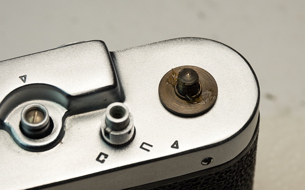
Let's reassemble the winding knob: Insert the small ring and washers, then place the plate with the collar on top. At this point, some grease needs to be applied so that the winding knob and film counter disc can turn easily (left).
Screw the rewind lock back on (bottom left). I was able to replace the small missing screw with one from my collection.
Now just reattach the speed wheel, accessory shoe, and rewind crank (bottom).
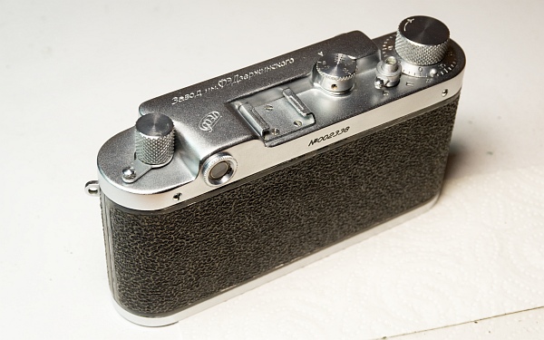
5. Ready!
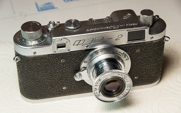
Finally finished!
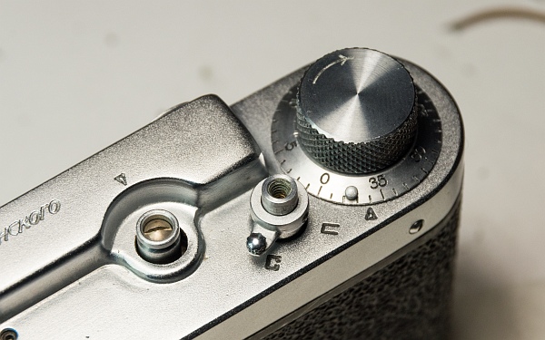
As you can see, the effort was definitely worth it! Thanks to the polishing cotton wool, the chrome shines like new again, and after adjusting the spring tension for the first and second curtains correctly, it can be easily tensioned and triggers quietly.
A notable feature of the FED 2a pre-production model is the extremely bright rangefinder spot. It looks as if it were illuminated.
