1. Removing the screen
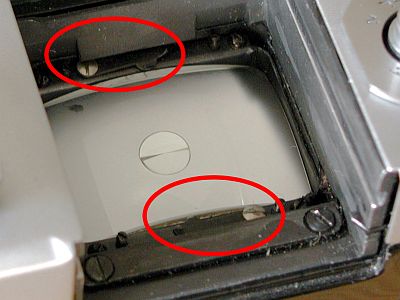
After unscrewing the lens, taking out the viewfinder and removing the rear panel, you can get started.
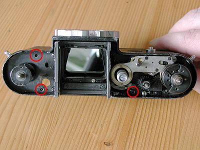
The focusing screen should be removed, otherwise it may fall towards you. It is clamped to the edge with two movable clips (see markings). Push the clips onto the black edge with a little pressure and remove the focusing screen.
2. Removing the film cutter
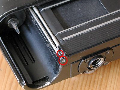
Two screws that hold the film cutter must be loosened. One is screwed into the housing from below, the other, smaller one at the top, holds the cover of the film cutter in place. Then you can access the screws of the shutter.
3. Opening the shutter box
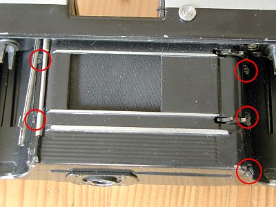
Bend the film cutter slightly to the side and unscrew the two screws on the left. There are 3 screws on the right-hand side that need to be removed. All 5 screws are the same.
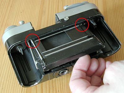
Tilt the case of the shutter box upwards and lift it out. Make sure that it does not catch on the teeth of the transport roller.
You can also open the box later once you have removed the cover. If you open it now, you can at least reach the adjustment screw for the locking spring of the first curtain.
4. Removing the rewind button
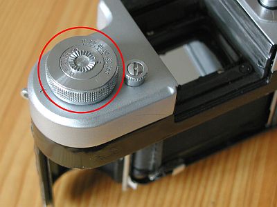
The rewind button comes off easily. Use pliers to hold the end inside the camera and simply twist the button off by hand.
It can be disassembled into further individual parts.
5. Dismantling the winding lever
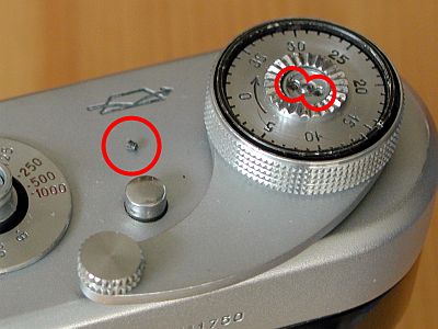
Now let's dismantle the winding lever.
Before we do this, let's quickly unscrew the speed knob. Note the current position in the tensioned state, loosen the two grub screws on the side and simply pull it upwards.
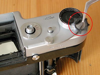
There is a washer in the middle of the tension lever that contains 2 tiny grub screws. These must be removed first. Note the tiny screw in the circle on the left.
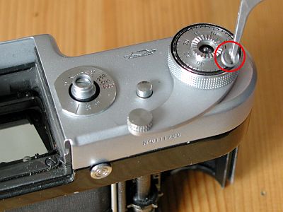
The washer can now be unscrewed using your thumb or a clamping tool.
The following parts can now be easily lifted out with tweezers. Note the sequence and position of the disks and springs.
- 1. disk of the counter
- 2. spring washer underneath (legs facing downwards)
- 3. larger black disk (bulge at the top)
- 4. small black disk
- 5. insert (open at the top)
- 6. spring washer for it (legs downwards)
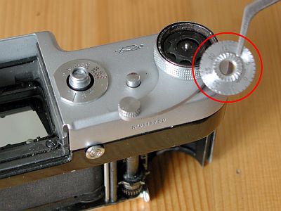
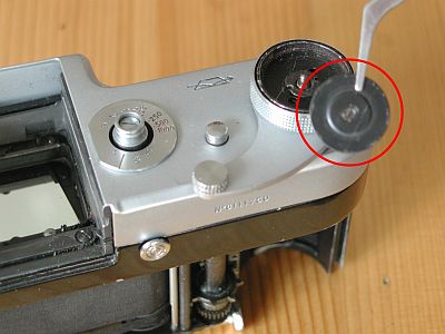
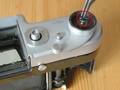
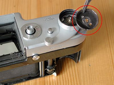
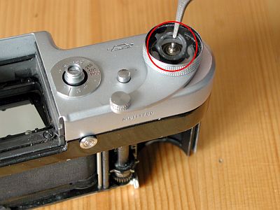
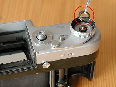
The brass washer is screwed on and can be quite tight. However, it can be easily unscrewed with a clamping tool or padded pliers.
Then simply remove the winding lever. Underneath is a washer that can only be fitted in one position. It is responsible for the clearance of the winding lever. The smooth side belongs downwards.
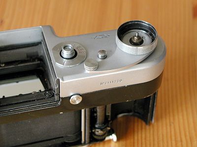
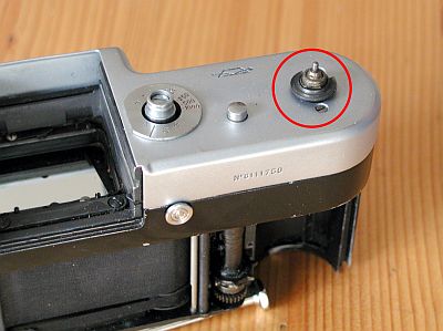
6. Remove cover
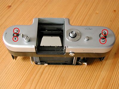
There are 2 screws on the left and 2 on the right, longer ones on the left and shorter ones on the right. These must be removed.
Remove the cover, its lower edge is stuck in a fold in the housing, it is a little difficult. Approx. 3 parts can fall towards you.
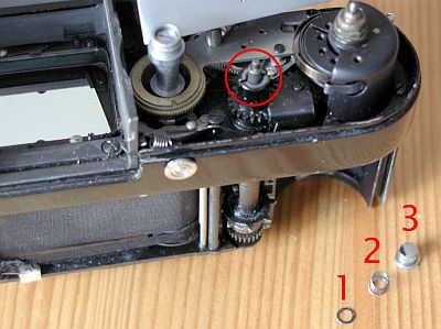
The approx. 3 parts are for unlocking the rewind lock (circle). There may be 0 to 2 washers (1), a spring (2) and the silver button (3).
When assembling, glue the silver button into the opening of the cover with a little grease so that it does not constantly fall out again.
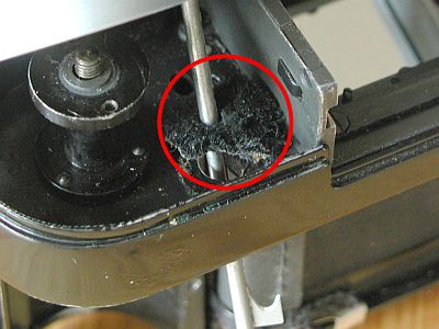
The question now arises as to how to get this film cutter out. There is an opening at the top of the housing which is sealed against light with a piece of velvet. The velvet has to be removed, then the cutter will fit through the opening.
Don't forget, the piece of velvet has to be glued back on when reassembling.
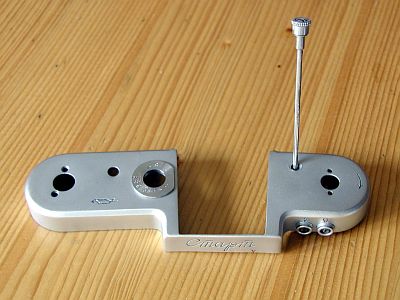
The cover with the film cutter. The upper part of the cutter is secured from the inside of the lid with a small grub screw.
If you have found an untampered start, there are still 2 cables from the lid through the housing to the bottom of the shutter. They are soldered to both flash contacts and to the shutter. Someone must have found the whole thing too strenuous - he simply snipped off the cables. Another possibility. So have a small soldering iron or a pair of pliers ready.
7. Remove shutter
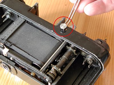
The small lever that locks the interchangeable prima must be removed. Simply take it in your hand and unscrew it.
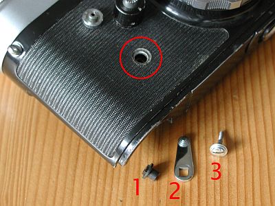
The self-timer lever must be unscrewed. Loosen the large screw (3), remove the lever (2) and the carrier (1). The carrier must be reinserted so that its two teeth hook onto the self-timer.
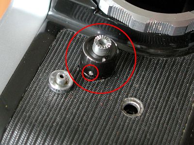
The trigger must be unscrewed. First loosen the small grub screw (small circle), then simply unscrew the black ring.
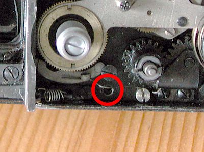
Now we are ready. 3 screws hold the shutter and the housing together. The second picture shows the right-hand screw in detail.
After loosening the 3 screws, the cap can simply be removed upwards. The teeth of the transport roller may hook a little.
8. Lubrication and adjustment
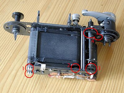
Back of the shutter.
Now you can finally reach the two screws for the spring tension of the closure curtains (1). The upper screw from this point of view is for the first curtain, the lower one for the second curtain.
The gear wheels found at 2, 3 and 4 should be cleaned of dirt and re-oiled. Don't overdo it with the oil, tiny amounts are enough.
You should now screw the speed knob and the tension lever back on for testing. It is sufficient to fit the lower disk and the tension lever and tighten the brass nut.
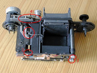
Front of the shutter.
The release mechanism is located at (1), the visible lever only triggers the mirror. The shutter release is located further inside and is triggered by the long lever in the release button. The lever can be released with a small screwdriver for testing in disassembled condition.
At (2) again a gear wheel for cleaning and oiling, (3) are the adjustment screws of the shutter. The gear wheels at (4) are the escapement of the long-time movement and must never be oiled.
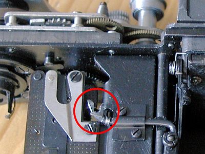
The lever for releasing the mirror is even larger. Above, the gears of the slow motion mechanism.
To release the shutter, a small screwdriver is inserted into the U-shaped opening of the lever after the mirror has been released and pressed relatively firmly against a small lever located at a depth of about 1 cm.
9. Bayonet ring
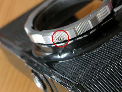
This screw holds the bayonet ring in position. If you loosen it 2 to 3 turns, the ring can simply be unscrewed. Pay attention to the position when unscrewing and screw back on at the same point.
10. Assembly
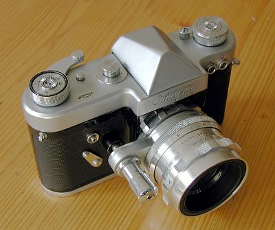
Assembly is carried out in reverse order.
If no parts are left over, the result is impressive.